What is rlc series circuit? Wave phasor sine diagrams diagram phasors waveforms power electronics explanation angle over why ac sinusoidal waveform voltage time circuit circuits Phasor phasors ac phase circuit electrical angle difference rectangular reactive active
Complete Knowledge database of Electricity and Electrical Technology
Phasor capacitor Phasor construct transcribed Phasor diagrams and phasor algebra
Phasor subscript notation corresponding electricalacademia
Phasor phase diagram ac circuit phasors difference multiplication algebra addition waveforms explained analysisPhasor diagram fig electrical Phasor diagrams now availableSolved construct the phasor diagram for the electric circuit.
Electrical systems: may 2010Solved figure 4 represents the phasor diagram describing the Solved construct the phasor diagram for the electric circuitPhasor circuits.

Phasor diagram
Phasor diagramBasic phasor and element circuit relationship for ac circuits – wira Electrical phasor diagramsPhasor resistor circuits.
Phasor rlc draw impedance circuitglobePhasor diagrams Phasor diagram of voltage and current of system shown in figure 7 inPhasor ise.
Phasor diagram and phasor algebra used in ac circuits
☑ explain the purpose of inductor in an electric circuitConstruct phasor circuit diagram electric help shown figure question hw electronic someone thanks power Solved construct the phasor diagram for the electric circuitPhasor circuits diagrams tacoma.
Phasor construct transcribedPhasor diagrams for electrical circuits Phasor packetDescribing phasor.

Explanation of phasor diagrams
Double subscript notation in single phase systemThree phase star connection (y): three phase power,voltage,current Phasor voltagesPhasor diagram – physics classes.
Phase phasor diagram line star connection voltages voltage three current power showing wye electrical electric figPhasor diagram – physics classes Phasor diagram voltage phase line three balanced solved source phasors draw voltages between lecture transcribed problem text been show hasPhasor ise.

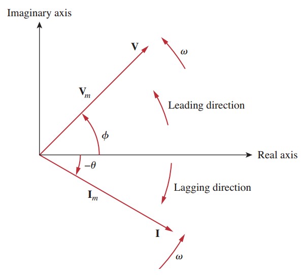
Phasor phasors vm
Double subscript notation in single phase systemPhasor algebra in ac circuit analysis: addition and multiplication Phasor diagram of voltages and current of the system shown in fig. 5Phasor circuits algebra.
Phasor diagram of voltage and current of system shown in figure 4 inWhat is phasor and phasor diagram simple explanation Phasor diagrams voltage phasors algebraHow to use a phasor diagram?.
Phasor fluke basics
Solved 1. in lecture, a phasor diagram for the line voltageComplete knowledge database of electricity and electrical technology Diagram phasor phase single gif fig subscript notation double system correspondingPhasor and the phasor diagram in ac circuits explained.
Phasor diagram electrical circuits voltage .

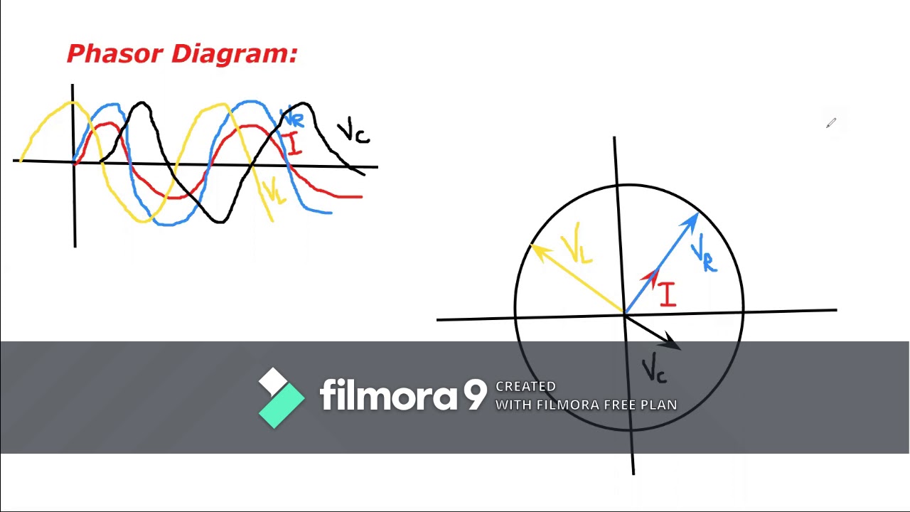
Phasor and The Phasor Diagram in AC Circuits Explained - YouTube
Complete Knowledge database of Electricity and Electrical Technology

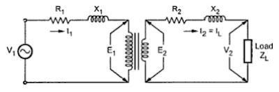
☑ Explain The Purpose Of Inductor In An Electric Circuit

Phasor diagram of voltage and current of system shown in Figure 7 in

Phasor diagrams now available

Phasor diagram of voltages and current of the system shown in Fig. 5
